📡 HB9V Technical Guide
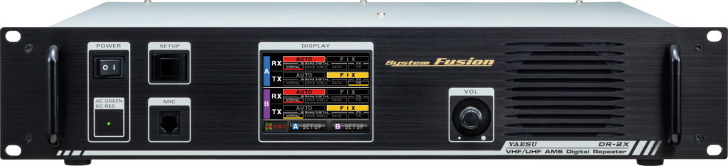
Guide to Resonant Cavities for the Yaesu DR-2X Repeater
Configuration with separate TX and RX antennas
The Yaesu DR-2X is a dual-band (VHF/UHF) repeater capable of transmitting up to 50W. When a repeater is installed with two separate antennas, one for transmitting (TX) and one for receiving (RX), you might think that filter cavities are unnecessary. That is a common mistake.
⚠️ Key point: Even with separate antennas, the physical isolation (typically 40-60 dB) is not enough to protect the receiver effectively. Cavities are still essential, but fewer are needed than in a single-antenna system with a duplexer.
🔍 Why are cavities needed?
1. Receiver desensitisation
Even though the transmitter works on a different frequency from the receiver (a 600 kHz offset on VHF or 7.6 MHz on UHF), the TX signal can overload the receiver's front end. A 50W transmitter produces such a strong signal that even the attenuation provided by two separate antennas lets enough energy through to “blind” the receiver.
2. Oscillator phase noise
The transmitter's oscillator is never perfectly “clean”. It generates phase noise, unwanted energy spread over several MHz around the carrier frequency. This noise can therefore end up directly on the receive frequency and mask weak signals.
3. Harmonics and intermodulation products
On a site with several transmitters, cavities also protect against intermodulation products generated by different frequencies mixing.
📊 Diagram: the problem without filtering
🔧 The two types of plunger cavity
Coaxial plunger cavities are tunable resonators. There are two basic configurations:
🟢 Band-Pass Cavity (Pass)
Passes the frequency it is tuned to and attenuates everything else.
Use: select only the wanted signal
🔴 Notch Cavity (Reject)
Rejects the frequency it is tuned to and passes everything else.
Use: eliminate a specific unwanted signal
📊 Diagram: frequency response of the cavities
Combined Band-Pass / Band-Reject (BP/BR)
There are also combined BP/BR cavities that provide both functions at once: they pass one frequency while rejecting another. These cavities are particularly effective but more complex to tune.
⚙️ Recommended configuration for the DR-2X
With a separate TX and RX antenna configuration, here is the optimal arrangement of cavities:
📊 Diagram: complete installation with cavities
Configuration details
| Chain | Cavity type | Tuned to | Function |
|---|---|---|---|
| RX | Notch (reject) | TX frequency | Rejects the TX signal leaking into the RX |
| RX | Band-pass (×1 or ×2) | RX frequency | Passes only the wanted signal to be received |
| TX | Band-pass (optional) | TX frequency | Cleans up the transmitted signal (reduces phase noise) |
💡 Important clarification: The notch on F-TX on the RX side and the band-pass on F-TX on the TX side are both tuned to the same TX frequency. The difference lies in their function: one rejects this signal (to protect the receiver), the other passes it cleanly (to transmit a clean signal).
📊 VHF vs UHF comparison
The number of cavities needed depends heavily on the band used:
VHF (144 MHz)
Only a 600 kHz shift, harder to filter
UHF (430 MHz)
7.6 MHz shift, easier to filter
| Parameter | VHF (2m) | UHF (70cm) |
|---|---|---|
| Standard TX/RX offset | 600 kHz | 7.6 MHz |
| Filtering difficulty | Harder (frequencies close together) | Easier (frequencies far apart) |
| Cavity size | Larger (~60-80 cm) | More compact (~30-40 cm) |
| Cavities (separate antennas) | 3-4 minimum | 2-3 minimum |
| Cavities with duplexer (single ant.) | 6-8 cavities | 4-6 cavities |
📐 Factors affecting the number of cavities
- Antenna spacing: The further apart the TX and RX antennas are (ideally several metres vertically), the better the natural isolation and the fewer cavities you need.
- TX power: The DR-2X can transmit up to 50W. At full power, more filtering is needed.
- Site quality: An isolated mountain site is “cleaner” than an urban site with many transmitters nearby.
- Required sensitivity: If you want to pick up very weak signals (DX), more rigorous filtering is needed.
- Antenna configuration: Cross-polarised antennas or directional radiation patterns can improve isolation.
🎯 Rule of thumb: With antennas 3-5 metres apart vertically and a careful setup, count on 3-4 cavities on VHF or 2-3 cavities on UHF. With a single-antenna duplexer, you would need almost twice as many.
🛠️ Practical installation tips
Connection order
On the RX side, place the notch (TX reject) first, right after the antenna. This removes the TX signal as early as possible in the chain, before it can overload anything.
Tuning
Tuning cavities requires a network analyser or, at the very least, a signal generator and a power meter. Each cavity must be tuned precisely to its target frequency. Poor tuning can degrade performance instead of improving it.
Insertion loss
Each cavity introduces some insertion loss (typically 0.5-1 dB per cavity). On the RX side, this slightly degrades sensitivity. It is a necessary compromise to get good rejection.
Cavity quality
Invest in quality cavities (Telewave, TX RX Systems, DB Products, etc.). Cheap cavities have a lower Q factor, which means less selectivity and more loss.
🎯 Practical case: 145.700 / 145.100 MHz repeater
Here is a concrete example of a configuration for a VHF repeater with the following parameters:
⚠️ Note: The 600 kHz shift on VHF is the most demanding in terms of filtering. The TX and RX frequencies are very close together, which requires high-quality cavities with a high Q factor to achieve sufficient separation.
Recommended configuration for this case
For a moderately polluted site (urban area with a park/forest), the following configuration is recommended:
| Chain | Type | Frequency | Qty | Role |
|---|---|---|---|---|
| RX | Notch | 145.700 MHz | 2 | Reject the TX (critical) |
| RX | Band-pass | 145.100 MHz | 1-2 | Filter out site pollution |
| TX | Band-pass | 145.700 MHz | 1 | Clean up the signal, protect neighbours |
📊 Diagram: installation for a 145.700 / 145.100 MHz repeater
🏆 Recommended cavity brands
For a professional installation with new equipment, here are the leading brands:
| Brand | Origin | Strengths | Price/cavity |
|---|---|---|---|
| Telewave 🥇 | USA | Thermal stability (Invar rods), very high Q | CHF 400-600 |
| TX RX Systems 🥈 | USA | Industry standard, very robust | CHF 350-550 |
| Sinclair 🥉 | Canada | Q-Circuit series popular with OMs | CHF 300-500 |
| DB Products | USA | Good quality, available second-hand | CHF 250-400 |
| EMR / Wacom | USA | Solid, good documentation | CHF 300-450 |
Recommended models for 2m VHF (144-146 MHz)
Telewave TPRC-1506
RECOMMENDEDType: Pass-Reject 6"
Band: 148-174 MHz (for 2 m, check that a version covering 144-146 MHz is available)
Power: 350W
Insertion loss: ~0.5 dB
~CHF 550-650
Telewave TPC-1506
BAND-PASSType: Bandpass 6"
Band: 148-174 MHz (for 2 m, check that a version covering 144-146 MHz is available)
Power: 350W
Insertion loss: ~0.4 dB
~CHF 450-550
Sinclair Q-2220E
GOOD VALUE FOR MONEYType: Pass-Reject Q-Circuit
Band: 132-174 MHz
Power: 250W
Special feature: designed for the amateur band
~CHF 400-500
💰 Estimated budget (new Telewave equipment):
| Qty | Model | Use | Price |
|---|---|---|---|
| 2× | TPRC-1506 | RX: Pass 145.1 / Reject 145.7 | ~CHF 1,200 |
| 1× | TPC-1506 | TX: Pass 145.7 | ~CHF 500 |
| TOTAL | ~CHF 1,700 | ||
🛒 Where to buy in Switzerland/Europe?
| Distributor | Country | Website | Notes |
|---|---|---|---|
| Wimo | 🇩🇪 Germany | wimo.com | European stock, fast delivery to Switzerland |
| Difona | 🇩🇪 Germany | difona.de | Good VHF/UHF range |
| UKW-Berichte | 🇩🇪 Germany | ukw-berichte.de | VHF/UHF specialist |
| The Antenna Farm | 🇺🇸 USA | theantennafarm.com | Large stock, ships to the EU |
| Telewave direct | 🇺🇸 USA | telewave.com | Made to order, 2-3 week lead time |
⚠️ Points to watch:
- Inter-cavity cables: the length is critical (electrical λ/2). Order them ready-made or have them made to measure.
- Tuning: plan for a network analyser (VNA). A NanoVNA at ~CHF 50 can be enough for basic tuning.
- Connectors: the professional standard is N female. The DR-2X has SO-239 sockets, so plan for adapters.
- Weather protection: for an outdoor installation, plan for an enclosure or a ventilated cabinet.
✅ Summary
For the DR-2X 145.700/145.100 MHz installation with separate antennas:
- YES, cavities are needed even with two antennas
- RX side: 2× TPRC-1506 (Pass 145.1 / Reject 145.7)
- TX side: 1× TPC-1506 (Pass 145.7)
- Recommended brand: Telewave (thermal stability, high Q)
- Total budget: ~CHF 1,700 (new equipment)
📡 Technical guide produced for HB9V
Radio Amateurs of Canton Vaud • 73 from HB9V