
📡 Amateur radio: the OCF dipole, a versatile multiband antenna
The off-centre-fed (OCF) dipole is a multiband antenna that is very popular with radio amateurs all over the world. This amateur radio antenna covers several HF bands (80, 40, 20 and 10 metres) with little or no tuning required. This complete guide explains how to build your own OCF dipole, from calculating the dimensions to final adjustment, to equip your amateur radio station.
📡 An introduction to the OCF dipole for radio amateurs
The off-centre-fed dipole is a multiband antenna that is very popular in the amateur radio community, particularly in Switzerland. This amateur radio antenna performs very well on several HF bands with little or no tuning required.
Unlike the classic centre-fed dipole, the OCF uses an offset feed point (usually at 36% of the total length) combined with a 4:1 balun, which gives optimal impedance matching on several amateur radio bands.
Works on 80, 40, 20 and 10m without a tuner
Affordable and accessible to any beginner radio amateur
Excellent performance for both DX and local amateur radio activities
Can be adapted to the space you have available
Low cost compared with commercial antennas
Acceptable SWR on the main bands
⚡ How the OCF antenna works
The OCF antenna used by radio amateurs (or hams) works on the principle of an optimised impedance. By moving the feed point to about 36% of the total length, you get an impedance of around 200 ohms at the feed point.
The 4:1 balun transforms this impedance to 50 ohms, which perfectly matches the characteristic impedance of the standard coaxial cables used in amateur radio.
📐 Basic calculation formula
Total length (metres) = 142.5 / lowest frequency (MHz)
Note: the imperial formula in feet (468 / frequency) can be converted by dividing by 3.28
This formula gives the length of a half-wave dipole. For the amateur radio OCF, we use this total length with an asymmetrical split:
- Long leg: 64% of the total length
- Short leg: 36% of the total length
📐 Calculating the dimensions for radio amateurs: 80-10 metre antenna
Example for the 80-metre amateur band
For an amateur radio OCF antenna covering 80 to 10 metres (the HF bands most used by radio amateurs), we use a frequency of 3.6 MHz (80 m band) as the reference:
Calculation in metres:
142.5 / 3.6 MHz = 39.6 metres
Leg lengths:
Long leg: 39.6 m × 0.64 = 25.35 metres
Short leg: 39.6 m × 0.36 = 14.25 metres
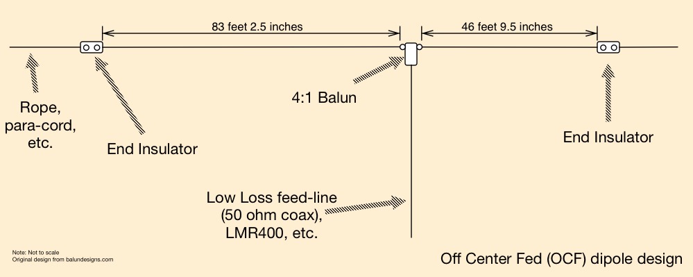
Schematic of the off-centre-fed dipole with a 36/64% split
Table of possible configurations
| Configuration | Base frequency | Total length | Long leg (64%) | Short leg (36%) |
|---|---|---|---|---|
| 160-10 m | 1.9 MHz | 75 m | 48 m | 27 m |
| 80-10 m | 3.6 MHz | 39.6 m | 25.35 m | 14.25 m |
| 40-10 m | 7.1 MHz | 20.1 m | 12.86 m | 7.24 m |
⚠️ Velocity factor: these calculations use a velocity factor of 0.975 for insulated copper wire. For the bare wire some radio amateurs use, adjust the dimensions slightly: bare wire gives slightly longer legs (cut long, then trim using an SWR meter).
🔧 Building the 4:1 balun
The 4:1 balun is the critical component of this amateur radio antenna. It transforms the impedance from 200Ω to 50Ω and prevents common-mode currents on the outside of the coax.
⚠️ Important: never connect the coax directly to the dipole without a balun! It is a common mistake among beginner radio amateurs.
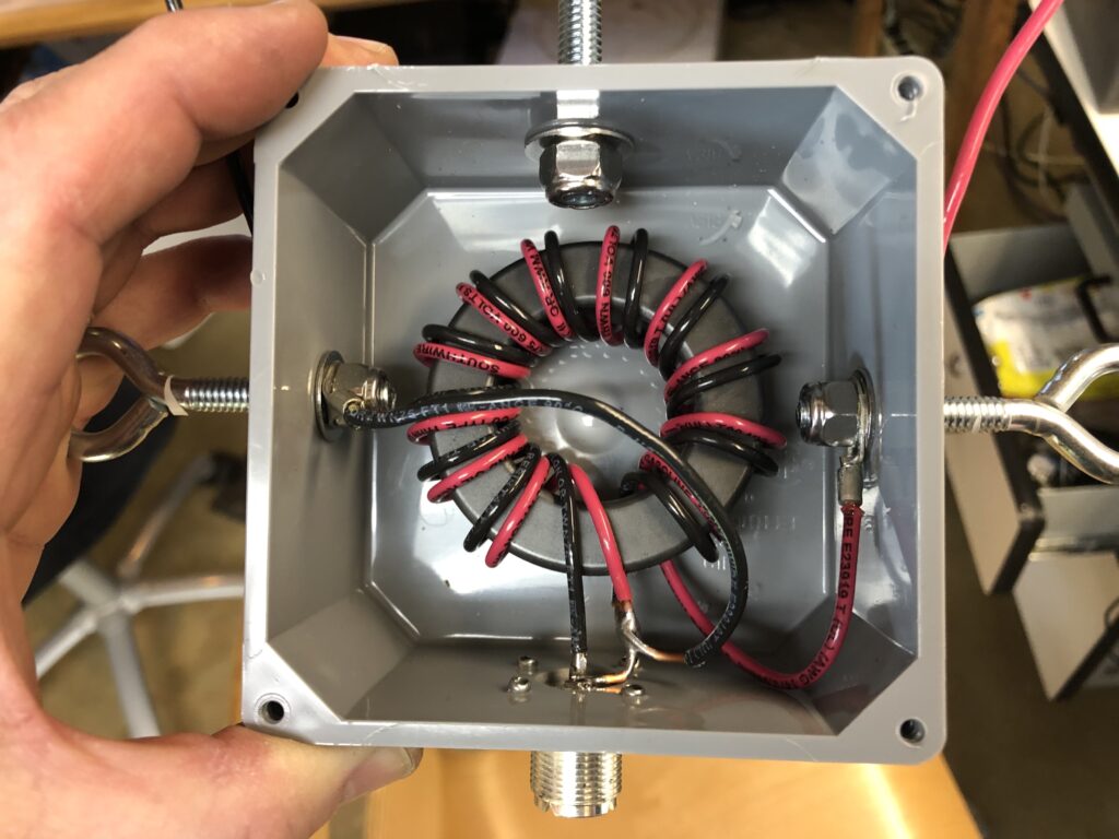
Home-made 4:1 balun in a weatherproof box with a ferrite toroid
Materials needed for the balun
📦 Parts list
- Ferrite toroid: FT240-43 or equivalent (permeability μ = 850, Mix 43)
- Enamelled wire: 1.2 metres of #14 AWG wire (or 1.5 mm² for European wire)
- Weatherproof box: approx. 10×10×5 cm, UV-resistant
- SO-239 connector: for the coaxial cable (UHF female type)
- M6 stainless steel bolts: with nuts and washers for the connections
- Weatherproof cable glands: or grommets with silicone seal
- Cable ties: to keep strain off the connections
- Silicone: for the final weatherproofing of the box
Detailed construction procedure
- Preparing the toroid: clean the ferrite toroid with isopropyl alcohol to remove any trace of grease. Lightly sand the edges if they are too sharp.
- Winding the wire: wind 12 turns of #14 AWG wire around the toroid. Keep the turns tight and evenly spaced. Count each pass through the centre of the toroid as one complete turn.
- Making the centre tap: at the middle of the winding (after 6 turns), carefully strip the enamel from about 1 cm of wire without cutting it. Use fine sandpaper to remove the enamel. This point will be the centre connection.
- Wiring to the diagram: connect one end of the winding to the short leg and the centre tap to the coax centre conductor; connect the other end of the winding, together with the coax braid, to the long leg.
- Mounting in the box: drill the holes for the SO-239 connector and the output bolts. Fit the connector, secure the toroid with cable ties and use ring terminals for the connections.
- Test before sealing: test the balun with an antenna analyser before closing the box for good. You should measure roughly 200Ω transformed to 50Ω.
- Final weatherproofing: apply silicone around all the cable entries. The balun will be exposed to the weather, so good sealing is essential for any radio amateur.
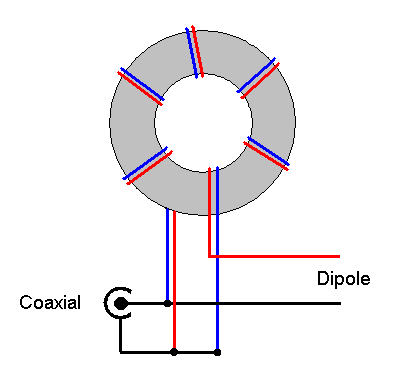
Wiring diagram of the 4:1 balun - both windings are in phase
💡 Winding tip for radio amateurs: before you start, mark the starting point on the toroid with a marker pen. After 6 turns, you should have gone roughly halfway round the toroid. This lets you check that the spacing is right.
⚠️ Watch the power: a balun wound on an FT240-43 toroid can handle around 500-800W PEP in intermittent SSB use. For the 100% duty cycle digital modes used by radio amateurs (FT8, RTTY), limit it to 200-300W to avoid overheating.
🔨 Building the OCF antenna
Materials for the antenna
📦 Complete parts list
- Antenna wire: 42 metres of insulated stranded copper #14 AWG (2 mm) wire
- 4:1 balun: built following the instructions above, or commercial
- End insulators: 2 high-strength insulators (ceramic or UV-resistant plastic)
- Coaxial cable: RG-213 or equivalent (50Ω, low loss)
- Support rope: paracord or UV-resistant braided rope
- PL-259 connector: for the connection to the balun
- Pulleys: optional, to make height adjustment easier
Construction steps
- Cutting the main wire: cut a wire with a total length of 42 metres. The extra 2.4 metres (compared with the 39.6 metres calculated) are for final adjustment and the connections.
- Splitting the legs: cut this wire into two sections: a long leg of 26.5 metres (with an extra 1.2 m for adjustment) and a short leg of 15.5 metres (with an extra 1.2 m for adjustment).
- Connecting to the balun: strip 1 cm at one end of each leg, pass it through the cable gland in the box, make a strain-relief loop (10 cm of slack), solder to the appropriate points and finish with heat-shrink tubing.
- Fitting the insulators: at the other end of each leg, pass the wire through the insulator but do not cut it yet. Leave 1.2 metres hanging on the long leg and 1.2 metres on the short leg for adjustment.
- Installing the antenna: the antenna can be installed horizontally (ends at the same height, ideal for DX) or as an inverted V (balun at the top, 90-120° angle between the legs, good for local contacts).
- Connecting the coax: use RG-213 cable, keep the length to a minimum, fit a lightning arrester at the entry point and make a drip loop before the balun input.
💡 Strain relief: never solder a wire that is under mechanical tension. Always make a strain-relief loop inside the balun box. It is an essential good practice for any radio amateur.
⚠️ Installation height: for best performance, install the antenna as high as possible. A minimum of 10 metres above the ground is recommended for the 80m band. Lower down, the antenna will still work but with a high radiation angle (less good for amateur radio DX).
🎯 SWR adjustment and optimisation
Adjustment procedure
- Initial measurement on 80m: with an antenna analyser or SWR meter, check the resonant frequency on 80 metres. The antenna should initially resonate below 3.5 MHz (around 3.2-3.4 MHz).
- Proportional adjustment: to move the frequency towards 3.6 MHz, trim off small lengths: first adjustment 15 cm in total at most (10 cm from the long leg, 5 cm from the short leg). Test after each adjustment!
- Multiband check: once 80m is adjusted, check the SWR on 40m, 20m and 10m. These bands should have an acceptable SWR without any further adjustment.
Calculating the frequency shift:
Every 1% reduction in length raises the frequency by about 1%
Example: to go from 3.4 MHz to 3.6 MHz (an increase of ~6%), reduce the total length by about 6% (≈ 2.4 metres in total)
SWR targets by band
| Band | Expected SWR | Comments for radio amateurs |
|---|---|---|
| 80 m (3.5-3.8 MHz) | 1.5:1 - 2.0:1 | Design band, minimum SWR |
| 40 m (7.0-7.2 MHz) | 1.2:1 - 1.5:1 | Excellent without a tuner |
| 20 m (14.0-14.35 MHz) | 1.3:1 - 1.8:1 | Very good, usable without a tuner |
| 17 m (18.068-18.168 MHz) | 2.0:1 - 3.0:1 | Tuner recommended |
| 15 m (21.0-21.45 MHz) | 1.5:1 - 2.5:1 | Usable, tuner optional |
| 10 m (28.0-29.7 MHz) | 1.3:1 - 2.0:1 | Good, usually without a tuner |
💡 A note on SWR on 80m: it is normal for the SWR on 80 metres to stay between 1.8:1 and 2.0:1 on an amateur radio antenna. This band is wide (500 kHz) and a dipole cannot cover the whole band with an SWR below 1.5:1. Choose your resonant frequency according to your modes: CW/digital (3.5-3.6 MHz) or SSB (3.6-3.8 MHz).
Factors affecting SWR
📏 Height above ground
The higher the amateur radio antenna, the less the ground affects the impedance. Aim for at least 10m for 80m.
🏢 Obstacles
Trees, buildings and other antennas can detune the OCF. Keep a reasonable distance from them.
🌍 Ground type
Conductive ground (damp, clay) versus dry ground (sand, rock) affects performance.
📐 Configuration
Horizontal versus inverted V: the angle of the V affects the impedance of the amateur radio antenna.
💡 Measurement tip for radio amateurs: always measure the SWR directly at the balun with a portable antenna analyser. The SWR measured in the shack can be misleading because of the coax transformation (transmission line effect).
⚠️ Safety during installation
⚠️ Essential safety rules
- Power lines: keep a minimum distance of 3 times the height of the power lines. Vital safety for any radio amateur!
- Falls: wear a safety harness when working at height. Never take risks.
- Weather: NEVER install an antenna during a thunderstorm or in strong wind.
- Help: always work with at least two people for the installation.
- Insulated tools: use tools with insulated handles near power lines.
Optimising performance
Orientation: to maximise amateur radio DX performance, orient the antenna at right angles to your preferred direction of communication. The main radiation pattern is broadside (perpendicular to the legs).
Inverted V configuration: if you use an inverted V configuration:
- Optimal angle between the legs: 90° to 120°
- Avoid too narrow an angle (<90°), which increases the SWR
- The ends should be at least 2-3 metres above the ground
Earthing: install a good earth at the point where the coax enters the shack. Use a coaxial lightning arrester to protect your amateur radio equipment.
🔍 Troubleshooting for radio amateurs
Common problems and solutions
| Problem | Possible causes | Solutions |
|---|---|---|
| High SWR on all bands | Faulty balun Open connection Incorrect length | Test the balun on its own Check continuity Recalculate dimensions |
| High SWR on 80m only | Antenna too short Strong ground influence | Lengthen proportionally Increase height |
| RF noise in the shack | Inadequate balun Common-mode currents | Check the balun Add ferrites Improve the earth |
| Poor performance | Antenna too low Nearby obstacles | Increase height Move away from metal obstacles |
📊 Performance and comparisons
✅ Typical performance for radio amateurs
- 80 metres: excellent local and national contacts for radio amateurs, DX possible in favourable conditions
- 40 metres: very good DX, one of the OCF's best bands. Worldwide coverage possible
- 20 metres: excellent amateur radio DX performance, low angle favouring long distances
- 15 and 10 metres: good DX performance during periods of high solar activity
Comparison with other amateur radio antennas
| Antenna type | Advantages | Disadvantages |
|---|---|---|
| OCF dipole | Multiband, no tuner, simple construction | Limited 80m performance, needs space |
| Classic dipole | Simple, effective, centre-fed | Single-band, tuner needed for other bands |
| End-fed | Very compact, flexible installation | Variable SWR, may need a counterpoise |
| Vertical | Omnidirectional, small footprint | Needs radials, high angle |
| Yagi beam | High gain, directional | Expensive, needs a rotator, complex |
📚 Resources for Swiss radio amateurs
Equipment suppliers (Switzerland/Europe)
🇨🇭 Phonicom.ch (Switzerland)
Swiss shop specialising in amateur radio equipment. Wide range of antennas, transceivers and accessories. Local service and advice.
🇩🇪 Wimo (Germany)
Wide choice of antennas and components for radio amateurs. Fast delivery to Switzerland.
🇩🇪 Funkamateur (Germany)
Quality baluns and complete antennas for European radio amateurs.
🇧🇪 Nortec (Belgium)
HF antenna specialist for radio amateurs. Recognised technical expertise.
Technical documentation
- ARRL Antenna Book - the complete reference on amateur radio antennas
- ON4AA.be - excellent resources on baluns for radio amateurs
- G3TXQ Balun Studies - in-depth studies of baluns
✅ Conclusion: your amateur radio OCF antenna
The off-centre-fed (OCF) dipole is an excellent compromise for any radio amateur looking for performance, simple construction and multiband versatility. Although building it takes a little care, particularly for the 4:1 balun, the end result is a reliable antenna that will serve radio amateurs faithfully for many years.
Critical for good amateur radio performance
Take the time to adjust it properly
Higher installation = better DX performance
It will never be perfect on every band
Don't hesitate to experiment with different heights, orientations and configurations. Every amateur radio installation is unique, and you will discover the specific characteristics of your antenna as you use it.
73 and happy building to all radio amateurs! If you have any questions or would like to share your experience of building an OCF antenna, don't hesitate to contact the Radio Amateurs of Canton Vaud (HB9V). The Swiss amateur radio community is always ready to help and share its experience with new radio amateurs.